


Voltage Drop Calculation Specs-2026

Voltage Drop Calculation Specs: A Complete Technical Guide
Voltage drop calculation specs play a critical role in electrical system design, ensuring safety, efficiency, and compliance with international standards. Whether designing residential wiring, industrial power distribution, or long-distance cable installations, understanding voltage drop specifications is essential to maintain performance and prevent energy losses.
This article provides a comprehensive overview of voltage drop calculation specs, including formulas, standards, influencing factors, and best practices.
What Is Voltage Drop?
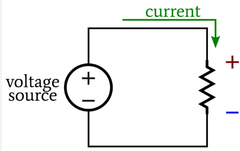
Voltage drop refers to the reduction in electrical voltage as current flows through a conductor due to resistance, reactance, or impedance. As electricity travels along a cable, some energy is lost as heat, causing a decrease in voltage at the load end.
Excessive voltage drop can result in:
- Poor equipment performance
- Overheating of conductors
- Reduced energy efficiency
- Premature equipment failure
Therefore, voltage drop calculation specs are defined to limit these losses within acceptable ranges.
Why Voltage Drop Calculation Specs Matter
Voltage drop specifications are critical for:
- Electrical safety
- System reliability
- Energy efficiency
- Regulatory compliance
Most electrical standards specify maximum allowable voltage drop limits to ensure that connected devices receive adequate voltage for proper operation.
Standard Voltage Drop Limits
While limits may vary slightly between standards, commonly accepted voltage drop limits are:
| Application Area | Maximum Voltage Drop |
|---|---|
| Branch Circuits | 3% |
| Feeders | 3% |
| Total System | 5% |
These limits are recommended by standards such as:
- NEC (National Electrical Code)
- IEC (International Electrotechnical Commission)
- BS (British Standards)
Exceeding these values can compromise system efficiency and safety.
Key Factors Affecting Voltage Drop
Voltage drop calculation specs depend on several technical parameters:
1. Conductor Length
Longer cables increase resistance, leading to higher voltage drop.
2. Conductor Material
- Copper: Lower resistance, lower voltage drop
- Aluminum: Higher resistance, higher voltage drop
3. Conductor Size (Cross-Sectional Area)
Larger conductors have lower resistance and reduced voltage drop.
4. Load Current
Higher current flow increases voltage drop proportionally.
5. System Voltage
Higher system voltage reduces percentage voltage drop for the same load.
6. Power Factor (AC Systems)
Low power factor increases voltage drop due to reactive components.
Voltage Drop Calculation Formulas
Voltage drop calculation specs rely on standard formulas depending on the system type.
DC Circuits
Voltage Drop (V) = 2 × I × L × R
Where:
- I = Current (Amps)
- L = One-way conductor length (meters)
- R = Resistance per unit length (ohms/meter)
Single-Phase AC Circuits
Voltage Drop (V) = 2 × I × L × (R × cosφ + X × sinφ)
Where:
- R = Resistance
- X = Reactance
- cosφ = Power factor
Three-Phase AC Circuits
Voltage Drop (V) = √3 × I × L × (R × cosφ + X × sinφ)
These formulas form the basis of voltage drop calculation specs used in engineering design software and manuals.
Voltage Drop Calculation Example
Given:
- Load current: 25 A
- Cable length: 40 m
- Copper conductor resistance: 0.00075 Ω/m
- Single-phase system
Calculation:
Voltage Drop = 2 × 25 × 40 × 0.00075
Voltage Drop = 1.5 V
If system voltage is 230 V:
Percentage Drop = (1.5 / 230) × 100 ≈ 0.65%
This is well within acceptable voltage drop calculation specs.
Voltage Drop in Long Cable Runs
For long-distance installations such as:
- Industrial plants
- Solar PV systems
- Transmission feeders
Voltage drop becomes a major design concern. Engineers often:
- Increase conductor size
- Use higher system voltage
- Improve power factor
- Shorten cable routes where possible
International Standards for Voltage Drop Calculation
IEC Standards
IEC 60364 recommends voltage drop limits similar to NEC and emphasizes efficiency and safety.
NEC (USA)
NEC Article 210 and 215 provide voltage drop recommendations (not mandatory but widely followed).
BS 7671 (UK)
Defines clear voltage drop limits and provides tables for conductor selection.
Adhering to these standards ensures compliance and optimal system performance.
Voltage Drop vs Power Loss
Voltage drop is directly related to power loss:
Power Loss (W) = I² × R
Higher voltage drop results in increased heat generation, which:
- Wastes energy
- Raises operating costs
- Shortens cable lifespan
Voltage drop calculation specs help balance conductor cost with long-term efficiency.
Best Practices for Voltage Drop Control
To meet voltage drop calculation specs, follow these best practices:
- Use adequately sized conductors
- Prefer copper over aluminum where possible
- Minimize cable length
- Improve load power factor
- Use higher distribution voltages
- Follow standard calculation methods
- Verify using software tools or tables
Voltage Drop Calculation Tools
Engineers commonly use:
- Electrical design software
- Manufacturer voltage drop charts
- Online voltage drop calculators
- IEC and NEC reference tables
These tools simplify compliance with voltage drop calculation specs.
Conclusion
Voltage drop calculation specs are a fundamental aspect of electrical system design. By understanding voltage drop limits, calculation methods, and influencing factors, engineers and electricians can design safe, efficient, and standards-compliant electrical installations.
Proper voltage drop calculations reduce energy losses, enhance equipment performance, and ensure long-term reliability. Whether for residential wiring or industrial power systems, adherence to voltage drop calculation specs is essential for modern electrical engineering.
For such comprehensive articles, click here Life Cables Blogs.